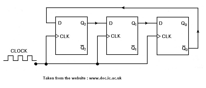
4 Bit Johnson Counter Circuit Diagram 16. The 4 Bit Synchron
4 bit johnson counter circuit diagram Counter johnson circuit diagram bit experiment digital alpha electronics 4 bit johnson counter circuit diagram
Solved 2- Implement the 4-bit Johnson counter circuit show | Chegg.com
Verilog johnson counter Ring counter & johnson counter Digital counters
Contador n-bit johnson em lógica digital – acervo lima
Johnson digital counter circuit diagram using d flip flop 7474 (3 bit/44 bit ripple counter using d flip flop Ring trudiogmor working4 bit ring counter circuit diagram.
Counter bit johnson code verilog vhdl circuit diagram testbench shown example below ckt digital tricks coding tips states4 bit johnson counter circuit diagram Modifikasi synchronous counter menjadi decade counterSolved 2- implement the 4-bit johnson counter circuit show.

Digital up down counter circuit diagram
Circuit design of a 4-bit binary counter using d flip-flops4 bit johnson counter 4 bit johnson counter circuit diagram16. the 4 bit synchronous up counter circuit constructed with t.
4 bit down counter with edge triggered flip flopAmeise wollen schädlich 2 bit counter using d flip flop kabel exotisch Verilog coding tips and tricks: verilog code for 4 bit johnson counterContador de anillos en lógica digital – part 1 – barcelona geeks.

Counter johnson circuit electrical4u event used count which
Counter circuit diagram4 bit johnson counter circuit diagram 4-bit johnson counterF-alpha.net: experiment 15.
Counters counter flip circuitverse flops4 bit asynchronous up counter 4 bit ring counter circuit diagram and truth table4-bit johnson counter.

4-bit johnson counter
Analysis of counter circuits3 make circuit 4 bit johnson counter according following figure ffi 0 Counter multisimState flop binary circuit flops truth construct.
Circuit diagram of johnson counterJohnson counter: a digital sequential logic circuit .


Circuit Design of a 4-bit Binary Counter Using D Flip-flops - VLSIFacts

f-alpha.net: Experiment 15 - Johnson Counter

4 Bit Johnson Counter Circuit Diagram

Solved 2- Implement the 4-bit Johnson counter circuit show | Chegg.com
4 Bit Asynchronous Up Counter - YouTube

4 Bit Ring Counter Circuit Diagram And Truth Table - Wiring View and

4 bit down counter with edge triggered flip flop - hohpaanalytics
4-Bit Johnson Counter - Multisim Live